Table of Contents
Ericsson / Alpha-American 4200C LED Sign
Overview
This is an Ericsson-branded, Alpha-American / Adaptive Micro Systems 4200C LED sign.
It is a programmable LED display commonly used for transit, public information, or industrial messaging systems.
- Model: 4200C
- Manufacture Date: 2004-04-08
- Power: 100–240V AC, 50/60Hz, 1.5A
- Status: Fully operational, displaying test message on boot. Unknown operational method.
- For indoor use only.
Microcontroller
The Microcontroller is TS80C32x2 which is compatible with Intel 8051.
Datasheet: https://ww1.microchip.com/downloads/en/devicedoc/doc4184.pdf
Intel MCS 51 MICROCONTROLLER FAMILY USER’S MANUAL: https://datasheets.chipdb.org/Intel/MCS51/MANUALS/27238302.PDF
Firmware
The device seemingly runs a custom firmware, the label on the epromm is “4200c CUST 1018-6008e”, and it displays CUST during boot.

The firmware is here:
The firmware is 128k (131072 bytes). SHA-1: e5e3bdad5e507f658a874d40483de60161152777 The Intel 8051 is designed as a Harvard architecture with two independend 16bit address buses. So the 128k dump is used as two separate ROMs of 64k each (PROM and XRAM).
Firmware Analysis
- Total ROM size is 128k
- The 8051 can address 2x 64k separately as PROM and XRAM
- The ROM is probably used as 2x 64k for PROM and XRAM (or maybe only PROM with bank switching?)
- The first 256 bytes of the lower 64k and upper 64k are similar (both contains “© COPYRIGHT ADAPTIVE MICRO SYSTEMS, INC. 1991” at the same offset)
- All the ASCII strings are in the lower 64k (except for the copyright message which is in both)
- According to Intel MCS 51 users manual: After reset, the CPU begins execution from location 0000H.
- Ghidra can read Intel 8051 binaries.
- The first three byes of low and high are 02 01 00 which is LJMP 0x0100 which suggest that both files are code and thus that PMEM is bank switched
- The real program seem to start at 0x0100 in both low and high
- Low has data from 0x0000 - 0xc3ef
- High has data from 0x0000 - 0x8ef3
- High has zero-patterns starting at 0x1000 or so which suggest that this is data and not code, but it not strings so maybe font data?
- In high at 0x0100 the code does some bit fiddling with IO ports and then does an infinite loops. While low has nops at the same addresses. So this probably triggers the bank switching to low, maybe with IO port P1.
Ports
 The sign has a RJ-style modular port on the back panel with:
- RS-232 IN
- RS-485 IN
- RS-485 OUT
It also has an IR sensor hidden behind a red sticker, visible when removing a panel.
Dongle
Communication
The sign probably uses the Alpha Sign Communications Protocol, which is:
- A structured serial protocol using STX/ETX framed packets.
- Allows sending:
- Text messages
- Control commands (clear, brightness, modes)
- Time-based messages
- Multiple signs can be connected via a RS-485 network
Serial Configuration
Suggestion for initial connection (untested):
- Interface: RS-232 IN (single device)
- Baud rate: 9600 or 19200
- Data bits: 8
- Parity: None
- Stop bits: 1
- Flow control: None
RJ-12 Pinouts, from left, clip down
- ground → GND TTL / db9 pin 5
- RS485 (+)
- RXD → TXD TTL / db9 pin 3
- TXD → RXD TTL / db9 pin 2
- RS485 (-)
- +5V (200ma max)
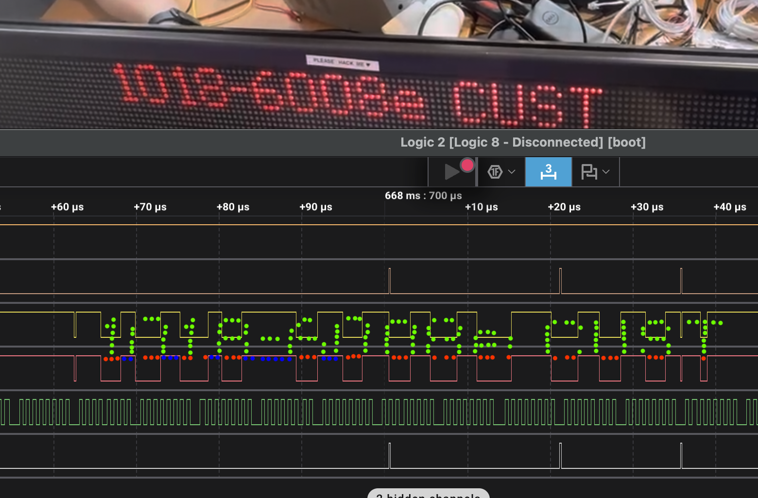
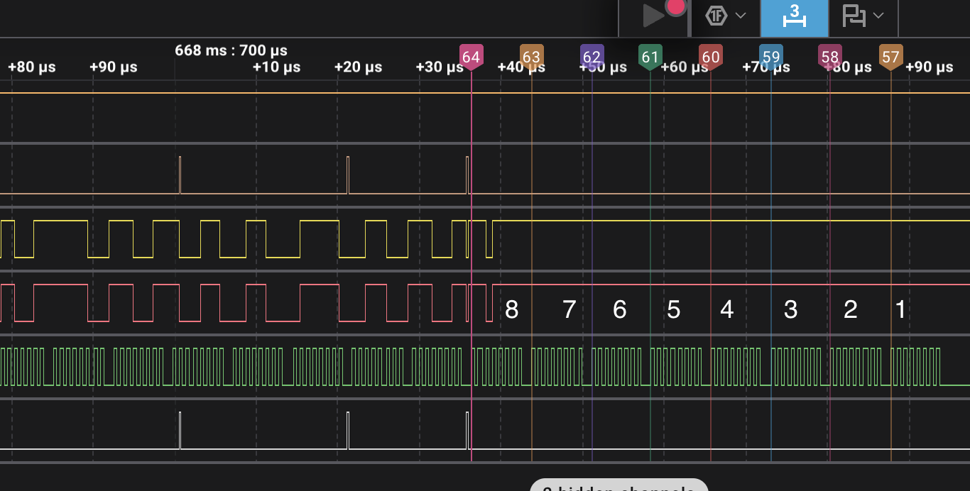
Logic analyser dump -- Cable between main board and driver board chain
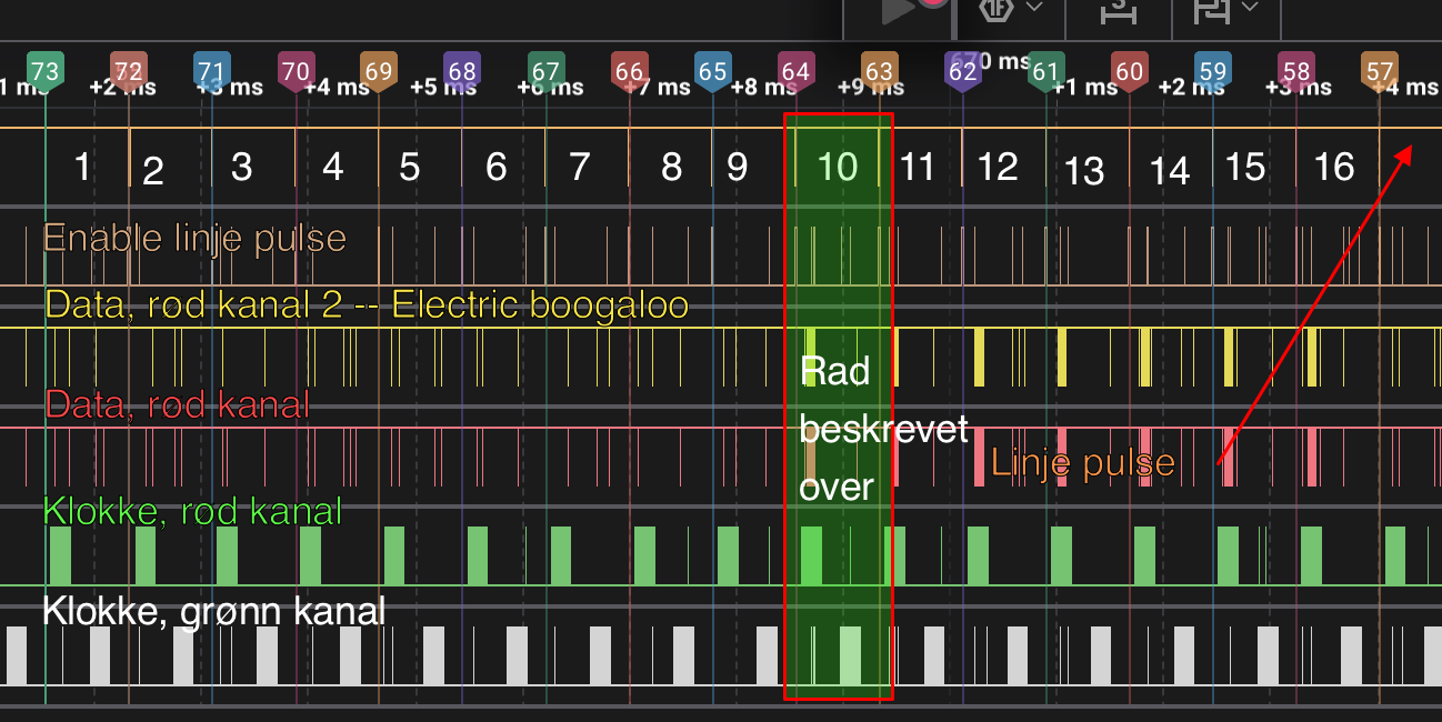
The driver board consists of: - 2x data lines (R channel + G channel) - 2x clock lines (R channel + G channel) - + 2 more lines
This analysis was performed on a dump with duplicate channels and some missing channels, so some blanks have been filled in by reasoning.
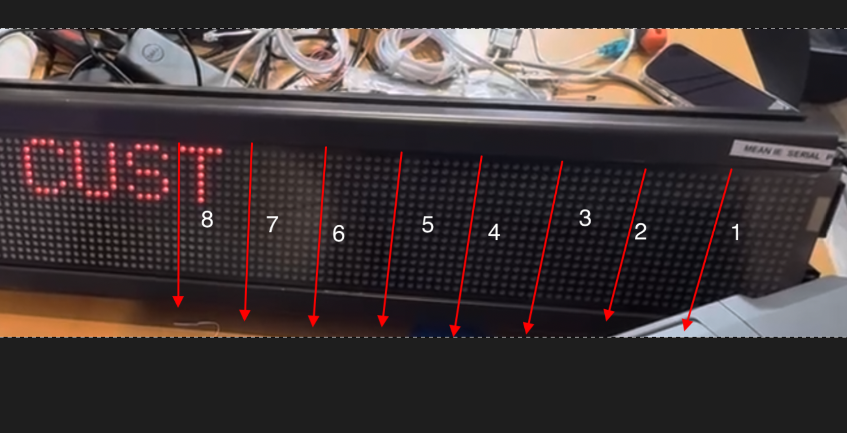
The total pixel surface of this board is 16 rows by 200 columns. We have 8 bits per module, with 25 modules per row. Total of 200 bits per row, per channel.
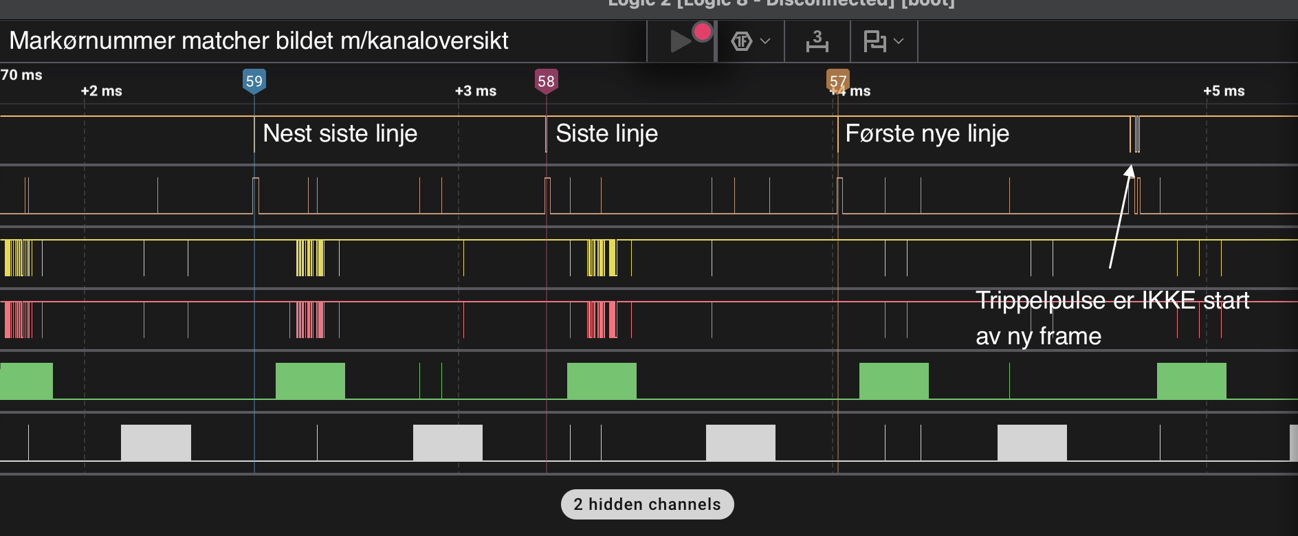
The entirety of one line is blasted out starting from the bottom row of the display, batched in groups of 8 bits (one-and-one matrix module, left to right). Once the red channel has been output, the same is done for the green channel on separate lines. Afterwards, the row selection is shifted one row up and the next line is output.
The line selection automatically wraps around, however it's suspected that the previous output latches are being reset using a pulse at the end of the _first line_ of a given frame.
Infrared
It seems that normal configuration of the sign is done over IR with a remote control or with an IR message loader attached via the RJ-12 connector.
The a quick look at the usual resources do not appear to have a capture of the remote.
Resources
- C programs to control Adaptive Micro Systems LED signs which may work or may not work with our sign


